
That's tedious at best.Ī few weeks ago Joe Carrick mentioned he keeps all his details on a single plan file and then references the details into the Layout file.

Drawing brick steps in softplan 2016 update#
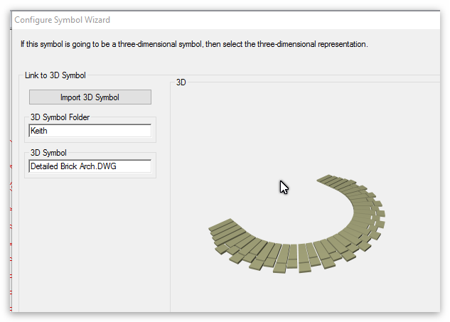
If anything ever changes or a code revisions requires a change to the detail, I open the original plan file, update the detail, make a cad block, and send it to the User Library to replace the old one, and delete the older detail. Like probably almost everyone else I've kept my details in the user library with the original saved as an individual plan file. It does work, but maintaining proper alignment to the dimensioned objects when inserting the symbol is tedious.Ĭurious, has anyone been working with the Replace Geometry feature of symbols? It has the potential to bring instanced objects into Chief to replace existing symbols that need to be updated to match current needs. Next best is to bring the dimensions in as separate symbols.

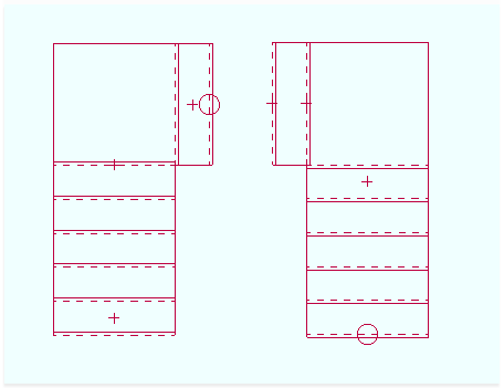
It would work now if Chief gave a bit more control over layer settings of the component parts of imported symbols. What I am looking to achieve is to be able to bring in symbols that contain dimensions of such things as framing hardware where the dimensions are already in place. Still, if you are going to go to the effort of bringing in the model, why not bring in the dimensions in 3D and simply pull the camera views in Chief?īeen working with this off and on with Chief for a while now. So far as I know this only works when importing a 3DS file though. They are no longer dimensions, but rather surfaces that can be displayed in 3D space in Chief. I suspect you already know that though, since it seems the objective is to arrive at this destination using chief.īTW, you can actually bring dimensions placed on a 3D UCS or Workplane into Chief now. These types of details produced from solid models has been around quite a while. Not only should the 3D dimensions be available in the 2D vjiews, there should also be hidden lines as dashed as well. Gene, it appears from the drawing that you posted that the 2D details done in Chief were created as separate drawings.Īgain, I appreciate the effort, but it kind of defeats the purpose of creating a 3D model only to have to draw the 2D details of the model. Nice to see the effort to bring 3D details into Chief. Of course you'll have to add the text manually. You'll have to draw the arrows manually but once you draw a couple all you have to do is copy and paste as necessary and they look pretty shnazzy in 3D. In the meantime, try using molding polylines drawn in 2D views. Anyway, there's not much you can do with it but it goes to show Chief is pretty stinking close. As long as your minimum display size is set high enough, the line length will also display WHILE IN 3D.īesides this, we also have temporary dimensions and dimensions lines that show up in 3D (when you select a cabinet for example). The arrows on either end of the line are displayed WHILE IN 3D.Ģ. While the line is selected you should notice 2 things.ġ. Now go into a 3D view and select that molding polyline. Now click the Convert Polyline tool, convert it to a molding polyline, and assign a narrow molding profile. Draw a line in plan view, include an arrow on both ends, set the arrow to maybe 9", and check Show Line Length. I should probably make a video about this at some point but it's funny, I think Chief is EXTREMELY close to having this capability already and they may not even realize it. Doing it this way, the representation in 3D is correct and any changes to the camera position don't require redoing anything except the text. I'm away from my computer right now so I can't post any examples, but I think the most efffective and best looking way to do this in Chief right now is using molding polylines with very thin molding profiles.


 0 kommentar(er)
